
With the recent Chamberlain API lockdown, I thought it might be interesting to tear down one of their controllers to see what makes it tick. Thankfully I happen to have a spare unit sitting new in the box. Why do I have a spare unit you might ask? The standard package comes with what Chamberlain calls a WiFi hub and a single door sensor. I have 2 garage doors, each with openers. At the time a spare door sensor was most of the cost of the whole package, so I just bought the whole thing again.
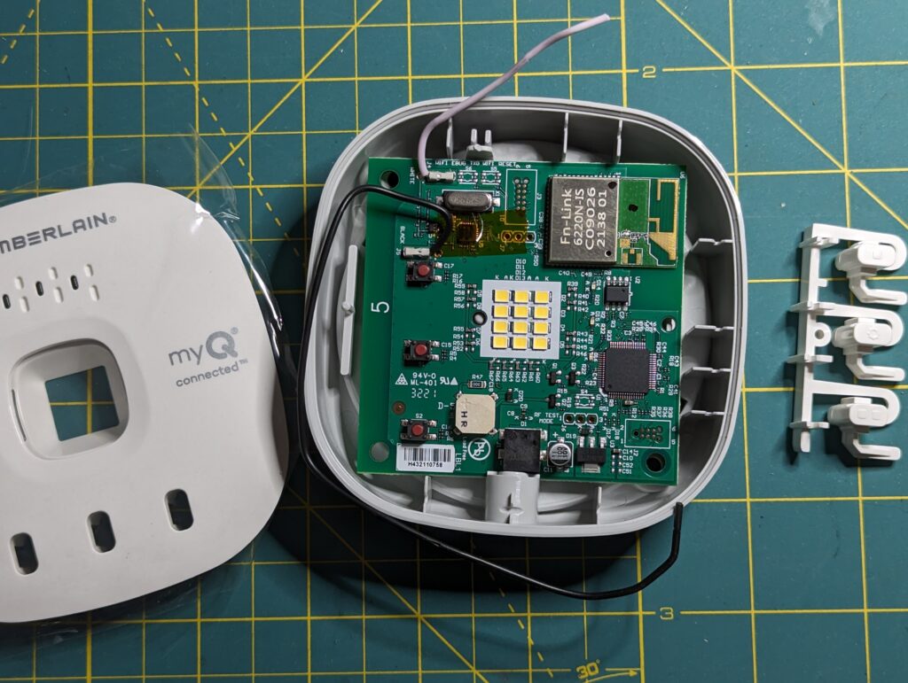
The WiFi hub is incredibly simple to disassemble. There are just 2 screws that hold the faceplate to the frame. Once you remove the faceplate, a single snap lever retains the main PCB. Once I had the main PCB separated from the frame, it was easy to pick out the core components.
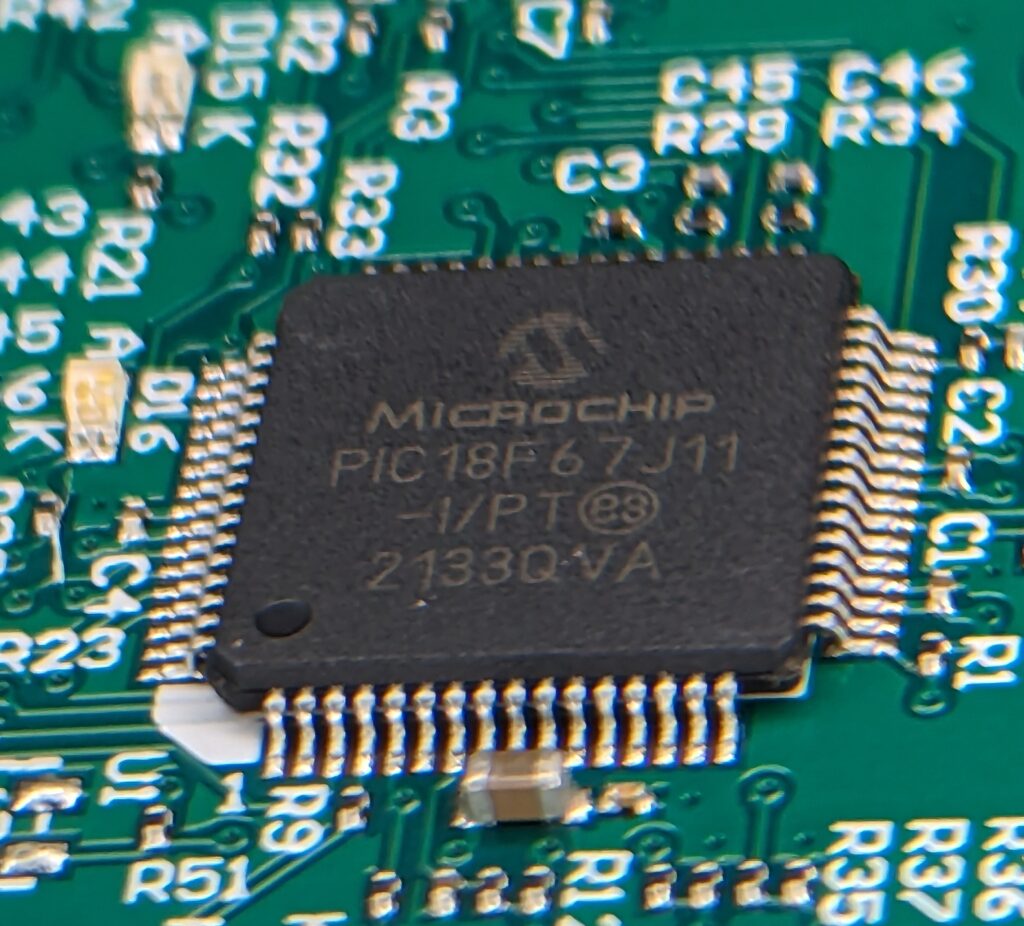
The system is based on a PIC18 microcontroller. In this case the Microchip PIC 18F67J11-1/PT. The PIC18 is a 16-bit RISC CPU compatible with the earlier PIC16. It has 128KB flash onboard and 4KB of RAM. While it’s no powerhouse, the CPU does offer 4 interrupt lines, 5 PWM, Parallel and Serial ports with SPI and i2C support.
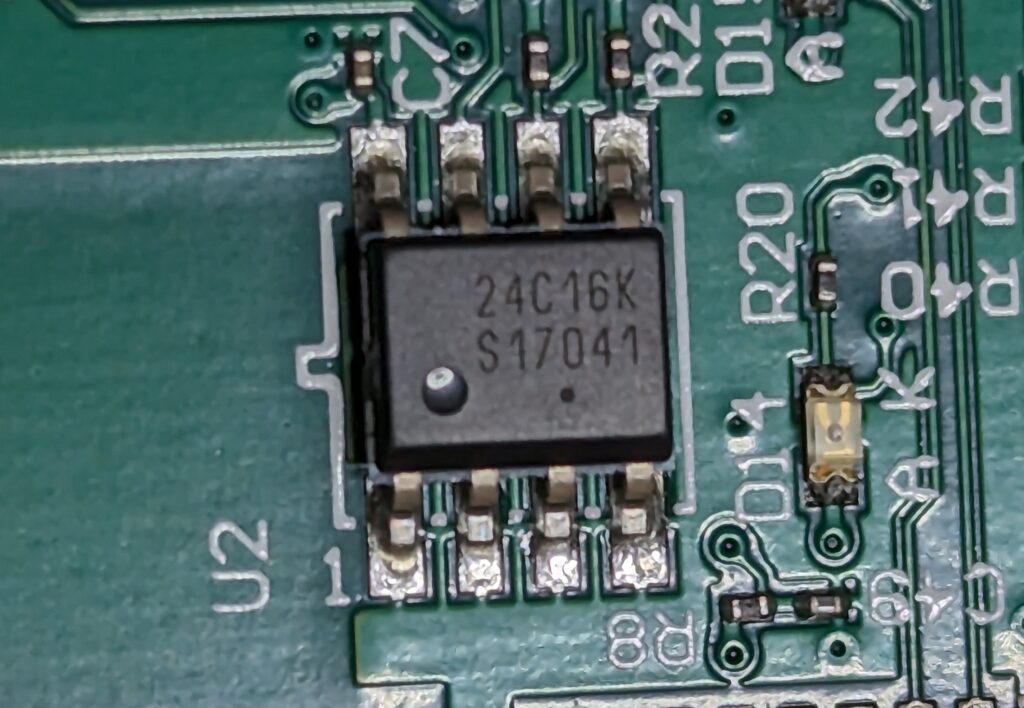
Linked to the PIC18’s i2C bus is a 24C16K SPI Flash ROM. I had a compatible harness for this and dumped the contents which were mostly empty. I’m assuming this rom is used for configuration data, possibly to store the opener codes programmed in during initial setup.
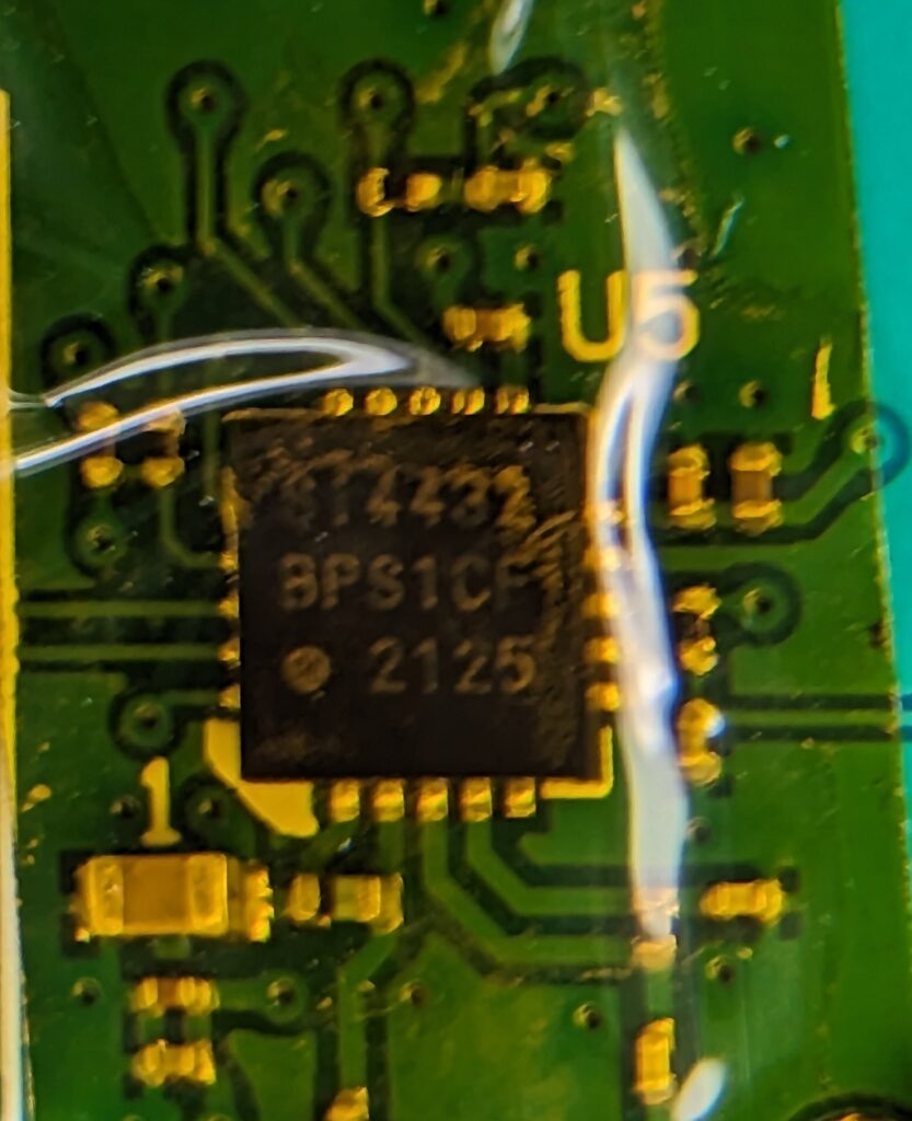
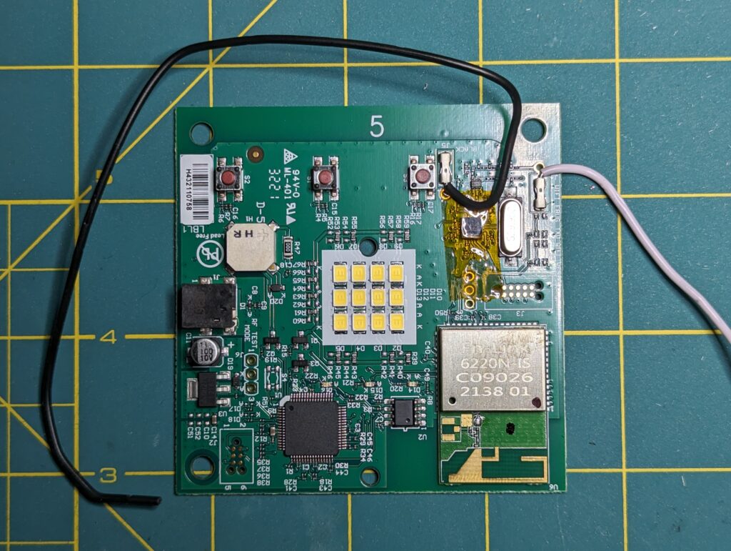
The remaining modules of interest were an Si4432 433mhz transceiver chip (left) and an Fn-Link 6220N-IS 2.4Ghz WiFi 5 module. (right) These enable comms with your network and most garage door openers.
So, what can we do with this knowledge? Well, given the CPU has a built-in flash, we could attempt to dump the contents of that storage and see if there’s anything useful we can decipher from it. There are test points on the board that appear to be connected directly to the CPU for programming. I’m going to attempt to verify this against the datasheet for the PIC18 and see if that’s the case. To be continued…