My Christmas wish list was very short this year, and a bit nerdy. (well ok… really nerdy) One of the things I had on my list was an oddly named open source bit of hardware called a Greaseweazel. This tiny little circuit board is a powerful tool that makes it possible
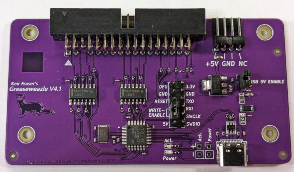
…to archive just about any type of floppy disk on a PC. You can build it yourself as a DiY kit, or order one pre-assembled. (I’d recommend ordering it pre-built unless you have a hot air rework station and are good with SMD soldering) When complete, the board connects to your computer via USB-C and to a floppy drive via a standard PC floppy ribbon cable. (you’ll also need a standalone power brick with a molex output, or a spare PC power supply for the floppy drive itself)
What makes the Greaseweazel so powerful is that it doesn’t really care about the format of the disk as it just reads the raw magnetic flux transitions straight from the read heads on the drive. (basically the raw analog signals recorded on the magnetic media itself) This can make it possible to extract data from disks that would otherwise be completely unusable. It also gives you the potential to make copies of damaged disks and potentially repair them at a later time digitally.
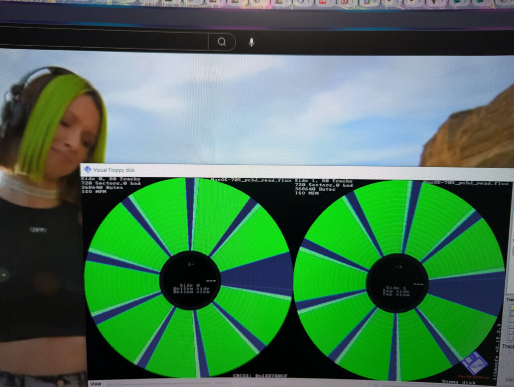
In addition to the native Greaseweazle software, there are several other open source toolkits that support the hardware and make working with certain types of disks easier. I’ve mostly been using FluxEngine and a windows tool called FluxMyFluffyFloppy which gives the native software a graphical interface. Another useful tool is HxC Floppy Emulator. (if you’ve ever seen tech youtubers working with graphical representations of floppy images, you’ve probably seen this)
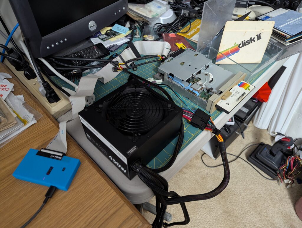
One of the first priorities I had for the Greaseweazle was backing up some of the quickly deteriorating Apple II disks in my collection. Many of them were too far gone to bring back, but I’m hopeful that some of the flux images I made can be reconstructed. I also 3D printed a case for the device to give it a little
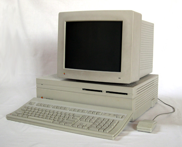
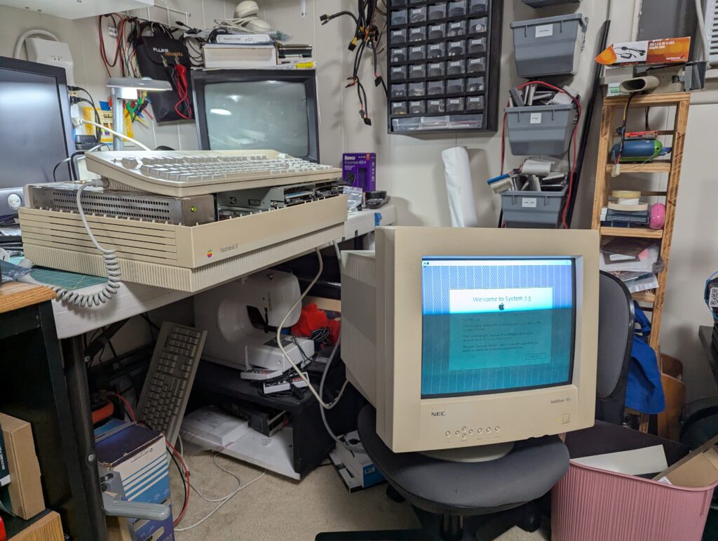
…protection and make it easier to handle. I also tried working with some 3.5in Apple Macintosh floppies, in both 800k and 1.44M varieties, but found this to be trickier than the older Apple II format. Unfortunately I also discovered some of these disks were also starting to deteriorate. Now that I’ve restored the Macintosh IIfx, I may just use it to make some disk images.